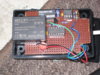
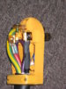
Hmm... seem to have lost an image there.Actually, (with a little help from Martin's blog) you can make really nice 24A NEMA 14-50 charger:
[noparse][/noparse]
Does the small enclosure in the center do anything besides generate the pilot signal? Is it adjustable?