Welcome to Tesla Motors Club
Discuss Tesla's Model S, Model 3, Model X, Model Y, Cybertruck, Roadster and More.
Register

Gen 3 Tesla and Gen 3 J1772 Wall Connector Install Write up with Photos!

This site may earn commission on affiliate links.
What is the point of power sharing if they are on separate panels? Who told you that 60A is your max total draw? If there is a limit on the sub panel then a breaker smaller than 50A should be used.

Also, does the breaker for the J1772 in the solar panel share the same wiring back to the main panel as your solar breakers? That doesn’t sound right, like there could be some situation where that wire ampacity is overdrawn.

The subpanel is connected to the main panel which comes thru a 200A main breaker. I chose 60A as a starting point before I calculate the power to see if I can go higher.

The J1772 is in the same subpanel as the solar breaker. This calculated OK to me because the solar panels would never draw power; my wall connector is pulling 7kw and the solar panel is generating 4kw, that means the subpanel would be pulling less than if there was no solar panels, similar concept as if the solar breaker is in the main panel with other circuits.
 
Gotcha. Mine came out of separate panels so didn't check if they can be wired up in a strings, that sounds fairly convenient as long as the total power available is sufficient.

What is the rating of the sub-panel ? If it was sized correctly for the main panel load then nothing prevents you from using its full ampacity to power the attached EVSE.

I am not clear why power sharing between the two EVSEs is being used here.
 
  • Like
Reactions: Watts_Up
This calculated OK to me because the solar panels would never draw power; my wall connector is pulling 7kw and the solar panel is generating 4kw, that means the subpanel would be pulling less than if there was no solar panels, similar concept as if the solar breaker is in the main panel with other circuits.

In so far as the busbar load is concerned, you add all the breakers
 
It looks like in your 3rd and 4th pictures you are using the same black wire for the two different hot legs. Should have been black and red, at this point I think you can fix it by adding red tape to both ends of one of them.

or . . . you could always run the two conductors in different directions, so that if you read the writing on them you can tell which one is which! 🥸

you won't find that in the NEC !
 
  • Like
Reactions: Stew-2 and MacO512
I was really curious on this. I sure thought you would have to mark one of the wires to distinguish it, but I did some searching. It looks like you don't have to.


Well I’ll be darned. Glad I made that post, even if wrong, because I just learned something new.
 
Thanks for your illustrations and sharing your experience!

It looks like in your 3rd and 4th pictures you are using the same black wire for the two different hot legs. Should have been black and red, at this point I think you can fix it by adding red tape to both ends of one of them. Be sure the red tape is at both ends of the same wire, not different ends of different wires ;)
I think since the circuit is 240VAC both hot wires in black color is fine.
 
After holes are drilled the wire that was originally used to run to the NEMA 14-50 socket was re-run thru the new hole I drilled (this wire had a romex sleeve which protects the wire in between the breaker panel and the wall connector). 3 wires total - 2 hot and 1 ground.

I also didn't need to touch the original breaker, since the last electrician already had a 50A for the NEMA 14-50.

View attachment 881517

How it looks on the other side. This is a "rear entry" meaning no wires above or below the wall connector!

View attachment 881518

All wired up! Note that Tesla instruction dictate 2 mounts for stud mount, but after doing that. I thought it was still a bit flimsy.. i'd do 3 mounting points next time.


View attachment 881520

Main body installed and secured! The lower hole was where the NEMA 14-50 outlet used to be, the hole just below the wall connector was a "oops" hole.. pro tip: measure twice, drill once.

View attachment 881525

Wifi Setup... Firmware upgrade, input Amps set, and since I have 2 wall connectors in my garage, I used the Power Sharing function. The two wall connectors are on two separate 50A circuits and communicate by Wifi. I set "Max Total Draw" to 60A between the two.


View attachment 881526


Last but not least, the finer details. Drywall repair/patch below, not pictured is the texture + primer + paint.


View attachment 881527
Looks good
 
What is the point of power sharing if they are on separate panels? Who told you that 60A is your max total draw? If there is a limit on the sub panel then a breaker smaller than 50A should be used.

Also, does the breaker for the J1772 in the solar panel share the same wiring back to the main panel as your solar breakers? That doesn’t sound right, like there could be some situation where that wire ampacity is overdrawn.
Even on separate panels, power sharing can help manage the total house main panel load.

If the Solar subpanel has a 50amp limit (going back to main) I think that is fine to have a 50 amp EV on it; it'll never have more than 50 amps going one direction or the other between the main and subpanel.
 
The install is very easy but I understand why some prefers an electrician to do it. Mine was close to the panel and only cost me $300.

My buddy on the other hand has to run it across the garage and he was quoted $1300 to do, he ended up running the wire himself (it cost him $300 for 50 feet I guess from Home Depot), then he called the electrician to do the wiring on the panel and the connector for $150 (less than 1 hour of work).
 
  • Like
Reactions: Rocky_H
The subpanel is connected to the main panel which comes thru a 200A main breaker. I chose 60A as a starting point before I calculate the power to see if I can go higher.

The J1772 is in the same subpanel as the solar breaker. This calculated OK to me because the solar panels would never draw power; my wall connector is pulling 7kw and the solar panel is generating 4kw, that means the subpanel would be pulling less than if there was no solar panels, similar concept as if the solar breaker is in the main panel with other circuits.
Is the breaker for the sub panel 200A or the breaker for the main panel 200A? Why would you choose something as a starting point THEN calculate whether it is too much or not? You should be calculating BEFORE installing the breakers and units.

Also, if the subpanel is designed for 4kw of solar, that’s only a 20A breaker. Something doesn’t add up.
 
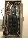
I have main braker with ground and neutral bond on same bar. Can I connect ground wire from wall charger there?
 

Attachments

  • IMG_5428.jpg
    IMG_5428.jpg
    531.5 KB · Views: 108
  • Like
Reactions: Rocky_H
I have main braker with ground and neutral bond on same bar. Can I connect ground wire from wall charger there?
Yes if this is the one main panel in your house. The conditions of electric code say that ground and neutral are to be tied together at ONLY ONE PLACE in the house, and that is in the main panel, so they are interchangeable there, and you frequently find grounds and neutrals intermixed on bus bars there. But outside of that main panel, and in any subpanels, they have to be kept separate.
 
  • Informative
Reactions: TunaBug
Yes if this is the one main panel in your house. The conditions of electric code say that ground and neutral are to be tied together at ONLY ONE PLACE in the house, and that is in the main panel, so they are interchangeable there, and you frequently find grounds and neutrals intermixed on bus bars there. But outside of that main panel, and in any subpanels, they have to be kept separate.
Thanks so much.