Welcome to Tesla Motors Club
Discuss Tesla's Model S, Model 3, Model X, Model Y, Cybertruck, Roadster and More.
Register

RGB Ambient Lighting project for Palladium Model S - lets do it

This site may earn commission on affiliate links.
Do you have a volt/ohm meter that you can use to ohm out (continuity checker) between the pins and the wires ? I think you know what pins you need. You just have to map it to the wire colors being used on the connector. Like the RGB wiring colors we are working around with these various lighting products we are connecting. You would THINK they would use red, green, blue and black wires !!!! In most cases they DO but the red wire does not map to the red signal :-(
Got 'er done. Another splitter I used in the past was easy to map as I could easily see each wire attached to each pin and had 18G wires. This one was impossible to dismantle to check, and uses super small gauge wires, like, 22G or so. The new one is a cleaner install though.

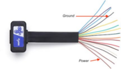
I thought I failed last night, but I was correct in that I just tripped the eFuse. While the colors do not match standard the standard OBD pins (which have never followed the red/black rule anyway), the cable bundle is flat, and laid out in the correct order (1,2,3...16).

The brown wire on the far end is power, #16, and #4 is ground. It looks black in the photo, but is actually yellow and black.
 

Attachments

  • 1713284354710.png
    1713284354710.png
    98.3 KB · Views: 7
I love the project. I used one of these boards a few years ago to add Z-wave compatibility to a Raspberry Pi I use for supervisory/control of my home generator. So easy to program. Once you finalize your code would you share ? This is not that complex to do and we may even be able to put a few units together to send out to the people here that may be interested. In my own search, I stumbled across the voltage sensor board you are using and noted it worked with an Arduino board. At first I thought....too complicated....but the more it is refining, it is not bad. Now I am thinking that if my SSR / filter hardware approach does not work I am going to pull my Arduino board out of my 'dead projects' basket as I removed it a year ago when I changed my home automation infrastructure.
I will absolutely share my code. Ill be sure to document it.
 
I will absolutely share my code. Ill be sure to document it.
Please excuse my ignorance, but how does one go about programming one of these devices?
Also, to summarize how you have this running: the device comes on with the Ambient lights, and if they shut off due to photosensitivety, you can override it and turn them back on. Is that correct?
 
Please excuse my ignorance, but how does one go about programming one of these devices?
Also, to summarize how you have this running: the device comes on with the Ambient lights, and if they shut off due to photosensitivety, you can override it and turn them back on. Is that correct?
TLDR: You hook it into a usb, then open a program like word, edit very few lines hopefully one or two, ideally none, click a button and voiala.

Long version: using arduino IDE select board, libraries, on a new sketch paste the code that I will share, upload the program to the arduino.

I will put up a video tutorial :) should be simple enough.
 
here is my code:
github
This should be publicly accessible. I will work on a tutorial over the weekend.
Arduino can be powered with a barrel connector or usb, I read that with usb bluetooth module from time to time doesn't start well. needing a recycle so I will go with the same source that powers the rgb lights

 
One more post with all the information:

PLEASE NOTE: this will ONLY work if you have a generic ELK-BLEDOM rgb controllers like the ones @Proppilot recommended.

List of materials:
Arduino R4 Wifi
Dupont cables
Voltage Sensor

wiring the sensor to the arduino:
from the 3 pins on the sensor:
+ to 3.3 v
- Ground
S -> Board pin A0

The other two sockets from the sensor should go to the OEM ambient lights. (You could also do OBD port or cigar port)


Flashing (installing the software into arduino) process:
Download arduino IDE
Connect the arduino via usb to the computer
Open arduino IDE
Select your arduino from here
1713320187828.png


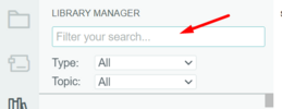
Install ArduinoBLE libraryby clicking here
1713320963302.png

Then type ArduinoBLE here and click install
1713321069227.png

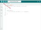
Copy the program from here to the IDE (replace everything)
1713320294219.png


Click on the arrow to upload this program to the arduino.
1713320360734.png


Process should take no more than 30 seconds once completed you can disconnect it and you should be good to go.

here's a link to some videos (upload maybe in progress) in which I show this in case I left anything out.

1713321229082.png


Mic DROPS!!!!
 

Attachments

  • 1713321023465.png
    1713321023465.png
    11.5 KB · Views: 4
  • 1713320233553.png
    1713320233553.png
    53.7 KB · Views: 2
updated the code with some enhancement as when I installed due to the PWM I saw readings of 0 and this can trigger the lights flickering, in the car I coded a loop for averaging the reads and that solved the problem. Project completed!
Do you think any Arduino would be OKAY IE the NANO ? I would think so but want to confirm.... again, I love the project. I am a Raspberry Pi addict and love coding Python for various home automation or aviation related projects for displaying weather on maps etc. This is the most complex but eloquent solution so I am compelled to build it just for fun BUT will still pursue my hardware trigger solution.

Right now I have three options to trigger.

I have purchased an ODB plug and built it out to bring two wires to the console area as a relay trigger (not going to use ODB power to actually power the lights - will still use charging tray power)

IF I can get my SSR project with the input RC filter to trigger reliably

The 'taekua trigger' which is super cool and I think simple enough that if there was interest, I would even be willing to build out a few units and send them out in 3D printed boxes

To all, keep installing and sending photos of progress or results !!!! Tony
 
I also wired out my new OBD splitter, attaching a barrel plug to it, and will use this as my trigger until such time that I can decide on either your SSR or the taekua trigger. I created a pigtail to come off the OBD with 2 diodes in-line to lower the voltage down a bit (in lieu of adding another buck converter).
 
Do you think any Arduino would be OKAY IE the NANO ? I would think so but want to confirm.... again, I love the project. I am a Raspberry Pi addict and love coding Python for various home automation or aviation related projects for displaying weather on maps etc. This is the most complex but eloquent solution so I am compelled to build it just for fun BUT will still pursue my hardware trigger solution.

Right now I have three options to trigger.

I have purchased an ODB plug and built it out to bring two wires to the console area as a relay trigger (not going to use ODB power to actually power the lights - will still use charging tray power)

IF I can get my SSR project with the input RC filter to trigger reliably

The 'taekua trigger' which is super cool and I think simple enough that if there was interest, I would even be willing to build out a few units and send them out in 3D printed boxes

To all, keep installing and sending photos of progress or results !!!! Tony
Hi, due to my code relying mostly on ArduinoBLE library I BELIEVE any of these boards should work:
I don't have any other, but as a hobby I plan to get another one. Props on the coding hobby, programming an arduino is more simple than a Pi, its just I am barely familiar with it now (about 20 hours in). Some libraries are very well documented, while others are barely documented and have bugs/glitches you can work around, such as the BLE library. In short arduino has two methods an init method and a loop method. All your code goes in there (C language). You can use copilot or chatgpt to help as I did. As a kid imagining that cars would be driving themselves and computers would be programing, would have been beyond a silly expectation. Alas chatgpt may not give you a full program, it can help you with simple tasks and solve problems/errors/questions that may arise. What a time to be alive!!

Yesterday was my first 2 hours ride with the solution slightly after sunset, the lights behaved as expected, when the sun went down the lights powered automatically, I tested on/off from the screen, they work immediately, the only scenario that at the moment I can't prevent is, before sunset (still some substantial sun light) having the rgb manually on, going under a bridge (OEM ambient lights goes on), and after exiting the bridge the rgb light goes off.

Because I love problems I like pain, I am going to buy one more arduino and I think I can solve this by making a phone app that communicates with Arduino, arduino keeps track of the state of the rgb lights and acts like the only interface to the lights, leaving lotus lantern app out of the picture.
It has been several years since I coded anything for a phone. DONT expect any of this during this year hahaha.

I was also looking into VOICE COMMANDS to the arduino using cyberon software which can do voice recognition with no training, but I am not sure about the state of that project as from the arduino official page, the links to the cyberon license page ($9 per device) led to a broken page. (EDIT) Page is up today so I guess this is very doable. From the models listed above, the 3 in bold seem to be currently supported for the speech recognition.

This has been a very fulfilling project with a lot of learning and I want to thank you guys for direction and motivation !!! I am humbled to be able to contribute with the "taekua trigger" and will be around for answering questions.

I realized one time I didn't answered one from @Proppilot about how I wired the floor for the front seats, truth is I haven't, I plan to do a custom y splitter cable from the dashboard lights and plug those there. the other option is getting another subcontroller and place it next to everything under the charging tray, but I'm afraid its already too crowded there.
 
Last edited:
Another way one could go is to monitor the CAN bus rather than tapping into the existing ambient lighting. I used a Teensy 3.6, which is another tiny Arduino processor, but it has two CAN bus ports (they have a newer version available now). With this, I watched the drive signals (Drive/Reverse/Parked) to display the correct state for the front of the car (must be white or amber while driving). Using the CAN bus allows clever choices, such as changing the LED color based on the steering angle, or showing the state of charge while charging. Ok, this is dramatically more complex than the great approach by taekua - but once you get into programming and have CAN bus signals, the sky is the limit as to what you can do!
 
Another way one could go is to monitor the CAN bus rather than tapping into the existing ambient lighting. I used a Teensy 3.6, which is another tiny Arduino processor, but it has two CAN bus ports (they have a newer version available now). With this, I watched the drive signals (Drive/Reverse/Parked) to display the correct state for the front of the car (must be white or amber while driving). Using the CAN bus allows clever choices, such as changing the LED color based on the steering angle, or showing the state of charge while charging. Ok, this is dramatically more complex than the great approach by taekua - but once you get into programming and have CAN bus signals, the sky is the limit as to what you can do!
These small controllers are incredible. Back in the day I started with BASIC Stamps and PIC chips. What one can get for $ 30 bucks now is more powerful than the computer on the lunar lander :cool:
 
I realized one time I didn't answered one from @Proppilot about how I wired the floor for the front seats, truth is I haven't, I plan to do a custom y splitter cable from the dashboard lights and plug those there.
I have a Nano ESP32 coming and it looks like it is supported by the BLE library. Love the ultra small footprint. I am a minimalist ! Roger that on the front floor seats. Now that we sourced the connectors from Amazon it took away any grief over extending wires or using other types of lights.
 
Another way one could go is to monitor the CAN bus rather than tapping into the existing ambient lighting. I used a Teensy 3.6, which is another tiny Arduino processor, but it has two CAN bus ports (they have a newer version available now).
Fantastic. That is a next level solution. You could trigger when only in DRIVE or whatever. These small uC units are tons of fun to play with. How do you watch the canbus signals ? If on a scope, what bandwidth scope is needed as minimum ?

@taekua how are you powering the Arduino ? Buck down converting from vehicle 16 volts to 5 ?
 
Another way one could go is to monitor the CAN bus rather than tapping into the existing ambient lighting. I used a Teensy 3.6, which is another tiny Arduino processor, but it has two CAN bus ports (they have a newer version available now). With this, I watched the drive signals (Drive/Reverse/Parked) to display the correct state for the front of the car (must be white or amber while driving). Using the CAN bus allows clever choices, such as changing the LED color based on the steering angle, or showing the state of charge while charging. Ok, this is dramatically more complex than the great approach by taekua - but once you get into programming and have CAN bus signals, the sky is the limit as to what you can do!
This sounds really cool. A friend of mine has a Mercedes EV whose ambient lights change to red while breaking. I was like, whoa, that crazy. But then, I could see that this could get distracting.
 
@taekua how are you powering the Arduino ? Buck down converting from vehicle 16 volts to 5 ?
I am powering with 16V via barrel connector, no need to use the buck, as the model I have supports up to 24 V.
1713462877536.png


I been given homework by @vcor !!! Thanks, better hobby than being ranked number 2 world wide in a fighting video game.

Finding the way to decode the CAN must prove interesting!
 
I am powering with 16V via barrel connector, no need to use the buck, as the model I have supports up to 24 V. View attachment 1039692

I been given homework by @vcor !!! Thanks, better hobby than being ranked number 2 world wide in a fighting video game.

Finding the way to decode the CAN must prove interesting!
I briefly read, the CAN is a standard bus with standard baud rate, reading from it should not be complex, decoding it might, as the data packets can be encoded in a proprietary way. There might be public databases from already known components, none the less this would be a very deep dive into a rabbit hole, specially for those like me that have little knowledge in electronics!
 
Another way one could go is to monitor the CAN bus rather than tapping into the existing ambient lighting. I used a Teensy 3.6, which is another tiny Arduino processor, but it has two CAN bus ports (they have a newer version available now). With this, I watched the drive signals (Drive/Reverse/Parked) to display the correct state for the front of the car (must be white or amber while driving). Using the CAN bus allows clever choices, such as changing the LED color based on the steering angle, or showing the state of charge while charging. Ok, this is dramatically more complex than the great approach by taekua - but once you get into programming and have CAN bus signals, the sky is the limit as to what you can do!
setting the ambient lights to breathing green while charging ----------solid when done but still plugged ....
ay ay ay ..... I wish I could spend more time on this.
 
  • Love
Reactions: Proppilot
Yesterday I noticed my ambient light turned on after I turned on the headlights manually, since it was not dark enough but I was driving on a one lane-two way highway and it was required. after that I was able to control the lights with the ambient light button on the screen. So conclusion, oem ambient lights seem to be photo sensitive as long as your headlights are off.