ENGINEERING STOP ! Sorry folks, as with experimentation problems arise. When I wired the version 2 of the door bin lights (the single LED for the light pipe) to the controllers being used for the strips I was noting problems with the lights flashing (the single LED door bin lights) and started troubleshooting. Then one smoked I suspected a wire short but as I look closer at the controller they came with, they are 3 volt LEDs and our controllers are 5 volts to the RGB lights so INCOMPATIBLE. Start your Amazon return on the second version of the door bin lights I posted. Not sure if it is as simple as putting a resistor on the v+ line to the emitter.... based on some reading, a 330 ohm resistor. I will try and report back.


Welcome to Tesla Motors Club
Discuss Tesla's Model S, Model 3, Model X, Model Y, Cybertruck, Roadster and More.
Register
Install the app
How to install the app on iOS
You can install our site as a web app on your iOS device by utilizing the Add to Home Screen feature in Safari. Please see this thread for more details on this.
Note: This feature may not be available in some browsers.
-
Want to remove ads? Register an account and login to see fewer ads, and become a Supporting Member to remove almost all ads.
You are using an out of date browser. It may not display this or other websites correctly.
You should upgrade or use an alternative browser.
You should upgrade or use an alternative browser.
RGB Ambient Lighting project for Palladium Model S - lets do it
- Thread starter Proppilot
- Start date
vcor
Tech Specialist
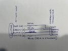
You will need multiple resistors as each LED (red/green/blue) has different voltages. Figure the red is 1.8v, green 2v, and blue 3.3v. Assuming 20 mA (perhaps more?) so the resistor has to be the difference from 5V to the LED voltage. For red (5-1.8v)/0.02 = 160 ohms. For green (5-2v)/0.02 = 150 ohms, and for blue (5-3.3v)/0.02 = 85 ohms. Resistors close to these values or larger ones will work fine. If you know the LEDs can handle higher currents, then you can recalculate with that current.
Also, 1/4W resistors should be fine.
Also, 1/4W resistors should be fine.
Yep, you are SPOT ON. Did a bunch of experience and curious why the strip (my version A above) is just fine. The reason is exactly what you state. In the strip light, I can see chip resistors to each of the R G B and + pins. I really love the idea of using the existing pipe lights in the door panelsYou will need multiple resistors as each LED (red/green/blue) has different voltages. Figure the red is 1.8v, green 2v, and blue 3.3v. Assuming 20 mA (perhaps more?) so the resistor has to be the difference from 5V to the LED voltage. For red (5-1.8v)/0.02 = 160 ohms. For green (5-2v)/0.02 = 150 ohms, and for blue (5-3.3v)/0.02 = 85 ohms. Resistors close to these values or larger ones will work fine. If you know the LEDs can handle higher currents, then you can recalculate with that current.
Also, 1/4W resistors should be fine.
Attachments
@Proppilot, While I think the idea of using the existing light pipe is pretty awesome, I gotta say, your first attempt at this looked pretty darn good as it was.
It seems to accomplish this, we would have to add 3 different resisters for each fiber optic source. 3 x 4 doors seems like a lot. Or, one triple set of resistors and 4 more runs. Either way, too many points of failure.
Forgive me, while I took some pretty advanced electrical engineering at Johns Hopkins, that was a LONG time ago, and I forgot EVERYTHING. Might there be a different fiber optic source that is compatible? Or, do all single light sources have this problem?
Last edited:
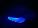
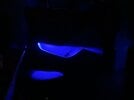
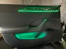
ENGINEERING RELEASE WITH UPDATE ! : okay based on the quick reply by vcor ") I did some testing both for heat and light output and have my recommendation. I compromised and used 150 ohm resistors in all three legs per the pen drawing above just to simplify the situation for many. I did put an 82 ohm in the blue leg and could not visually tell the difference so a 150 ohm in the red green and blue legs which are the red green and white wires coming out of the emitter. I then did a dark room test on the RGB strip (option A mentioned prior) and the single emitter using the existing light pipes that are in the doors (far more eloquent) and have attached photos. I find the RGB strip too bright and possibly distracting and the single emitter just perfect so I am really happy to proceed down this path.
I did some testing both for heat and light output and have my recommendation. I compromised and used 150 ohm resistors in all three legs per the pen drawing above just to simplify the situation for many. I did put an 82 ohm in the blue leg and could not visually tell the difference so a 150 ohm in the red green and blue legs which are the red green and white wires coming out of the emitter. I then did a dark room test on the RGB strip (option A mentioned prior) and the single emitter using the existing light pipes that are in the doors (far more eloquent) and have attached photos. I find the RGB strip too bright and possibly distracting and the single emitter just perfect so I am really happy to proceed down this path.
Last week I ended up breaking the light pipe in my drivers door trying to remove it and ended up purchasing some 6 mm acrylic downing and fashioning a new light pipe with my heat gun. Had to do some research on how to get light to exit the pipe along the long side and all you do is use sandpaper and sand the upper or opposite surface of the pipe. This creates an interference that the light reflects off of down into the bin. You can see a major difference before and after sanding the top of the pipe. NOTE : this is only IF you break your light pipes which should not be the case now that you know that if you try to remove them.....they will break ! You just have to take the OEM existing white emitter off the top of the pipe and replace with the new one.
And the project moves forward.....
I did some testing both for heat and light output and have my recommendation. I compromised and used 150 ohm resistors in all three legs per the pen drawing above just to simplify the situation for many. I did put an 82 ohm in the blue leg and could not visually tell the difference so a 150 ohm in the red green and blue legs which are the red green and white wires coming out of the emitter. I then did a dark room test on the RGB strip (option A mentioned prior) and the single emitter using the existing light pipes that are in the doors (far more eloquent) and have attached photos. I find the RGB strip too bright and possibly distracting and the single emitter just perfect so I am really happy to proceed down this path. Last week I ended up breaking the light pipe in my drivers door trying to remove it and ended up purchasing some 6 mm acrylic downing and fashioning a new light pipe with my heat gun. Had to do some research on how to get light to exit the pipe along the long side and all you do is use sandpaper and sand the upper or opposite surface of the pipe. This creates an interference that the light reflects off of down into the bin. You can see a major difference before and after sanding the top of the pipe. NOTE : this is only IF you break your light pipes which should not be the case now that you know that if you try to remove them.....they will break ! You just have to take the OEM existing white emitter off the top of the pipe and replace with the new one.
And the project moves forward.....
Attachments
It ended up being pretty easy. As you have to solder a new connector onto the single LED emitters, you just put a 150 ohm resistor in series with the red green and white wires (not the black) and put a bit of heat shrink over each.@Proppilot, While I think the idea of using the existing light pipe is pretty awesome, I gotta say, your first attempt at this looked pretty darn good as it was.
It seems to accomplish this, we would have to add 3 different resisters for each fiber optic source. 3 x 4 doors seems like a lot. Or, one triple set of resistors and 4 more runs. Either way, too many points of failure.
Forgive me, while I took some pretty advanced electrical engineering at Johns Hopkins, that was a LONG time ago, and I forgot EVERYTHING. Might there be a different fiber optic source that is compatible? Or, do all single light sources have this problem?
This is fantastic news. I see 1/4 and 1/2 Watt resistors online. Any particular ones you recommend?ENGINEERING RELEASE WITH UPDATE ! : okay based on the quick reply by vcor
Last week I ended up breaking the light pipe in my drivers door trying to remove it and ended up purchasing some 6 mm acrylic downing and fashioning a new light pipe with my heat gun. Had to do some research on how to get light to exit the pipe along the long side and all you do is use sandpaper and sand the upper or opposite surface of the pipe. This creates an interference that the light reflects off of down into the bin. You can see a major difference before and after sanding the top of the pipe. NOTE : this is only IF you break your light pipes which should not be the case now that you know that if you try to remove them.....they will break ! You just have to take the OEM existing white emitter off the top of the pipe and replace with the new one.
And the project moves forward.....
1/4 watts are fine. I am definitely starting to sound schizophrenic in this thread as I just completed the drivers door full install and wiring. Depending on the brightness one likes, if you dim the upper door strip down all the way, there is barely any visible light in the bins. With the controller at 100% brightness the bin level is perfect and with the controller at minimal brightness the strip light level is perfect (for me). I have the drivers side doors both fished back to the console area and buttoned up.This is fantastic news. I see 1/4 and 1/2 Watt resistors online. Any particular ones you recommend?
A multi zone controller would be perfect but the kit I have does not do it. Subsequently, I have found dual zone controllable kits on Ali for these car lighting systems. I have learned a ton (or should have done better research) about these kits.
I just did some testing with TWO main controllers to see if I could split some subs off onto each one and control separately. Indeed I could. I was able to pair one remote with one MAIN and another remote with another MAIN. Worked perfectly and I had two controllers connected in the APP. Once I powered everything off and back on, all the remotes latched onto one controller so NO JOY.
Keeping the bin lighting as the single emitter would mean either getting another kit with dual zones or going back to my first option of the strip lights. Not as eloquent however the strips are pretty much invisible. I tested in a dark room with the strips and with the light level on minimum, there was as much light off the strip as the single emitter and light pipe gave on 100% level SO......and somewhat defeated to find an optimal solution, I am going back to the strip lights....
Last edited:
Project update : I have learned a ton, tried a bunch of things and have landed up using the equipment that I included links to in the document I posted.
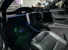
The strip lights in the door bins are a better light intensity match to the upper strips so when you dim, you get a far more equal distribution of light between the two locations. You can see in the photo with the green illuminated that it is a much better match.
BUILD TIP : for the FRONT doors, use the thin VHB tape and attach the acrylic strip to the door itself and NOT the removable trim piece. Why ? Because you have to remove that upper trim to remove a door bolt and the RGB strip comes with it and can crimp or damage the wiring that is going back into the door. With the strip attached to the door itself, the trim can go on and off independently. On the REAR doors attach the RGB strips to the trim piece as it is a remove and replace once deal.
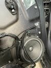
Showing a picture of where I brought the power cable out in the rear door and added a barrel connector. In the door frame, remove the rubber boot at the door and car frame by pulling it out and you get MUCH easier access to fishing a wire through.
Some background on my car. It was the first Palladium delivered in Eastern Canada so a very early build. I had an airbag fault within two weeks that a Ranger rectified by cleaning a ground however over the next almost two years, the car was back at Tesla 15 (yes fifteen) times for SRS faults. I believe over that time every airbag and controller was replaced. What fixed it ? They replaced the entire body harness and when doing so, found that a wire had been crimped by a bolt during manufacturing. It was a frustrating process for sure and Tesla made good with me.
TODAY I somehow ended up triggering an SRS failure RCM2_a196_driverABAVOpen which is the driver Active Vent (I have no idea what this is, does anyone ?). I must have jogged or loosened a connector or something. I put the car in Service mode and went back through where I worked and reset the connectors and the fault cleared. PTSD back to the SRS-fest I had prior.
So I am probably 20 hours into the project and have only completed the front and rear left doors. Many hours learning and playing with things before going to the car (IE the bin lights). The front door took 3 hours to install as I had to try a bunch of things and the rear was about an hour so with all of the learning and sharing in this thread I would estimate someone would need two 8 hour days to do the project AND I would suggest you pull all the trim and doors at the same time so you get access to everything. I have not and it has added a bunch of time.
Next is right side doors and then dash, console and then footwells. I built a small circuit with a 12 volt socket plug and the buck converters and my spare master controller so I can test each cable once it is home run to the console.
Onward.....
The strip lights in the door bins are a better light intensity match to the upper strips so when you dim, you get a far more equal distribution of light between the two locations. You can see in the photo with the green illuminated that it is a much better match.
BUILD TIP : for the FRONT doors, use the thin VHB tape and attach the acrylic strip to the door itself and NOT the removable trim piece. Why ? Because you have to remove that upper trim to remove a door bolt and the RGB strip comes with it and can crimp or damage the wiring that is going back into the door. With the strip attached to the door itself, the trim can go on and off independently. On the REAR doors attach the RGB strips to the trim piece as it is a remove and replace once deal.
Showing a picture of where I brought the power cable out in the rear door and added a barrel connector. In the door frame, remove the rubber boot at the door and car frame by pulling it out and you get MUCH easier access to fishing a wire through.
Some background on my car. It was the first Palladium delivered in Eastern Canada so a very early build. I had an airbag fault within two weeks that a Ranger rectified by cleaning a ground however over the next almost two years, the car was back at Tesla 15 (yes fifteen) times for SRS faults. I believe over that time every airbag and controller was replaced. What fixed it ? They replaced the entire body harness and when doing so, found that a wire had been crimped by a bolt during manufacturing. It was a frustrating process for sure and Tesla made good with me.
TODAY I somehow ended up triggering an SRS failure RCM2_a196_driverABAVOpen which is the driver Active Vent (I have no idea what this is, does anyone ?). I must have jogged or loosened a connector or something. I put the car in Service mode and went back through where I worked and reset the connectors and the fault cleared. PTSD back to the SRS-fest I had prior.
So I am probably 20 hours into the project and have only completed the front and rear left doors. Many hours learning and playing with things before going to the car (IE the bin lights). The front door took 3 hours to install as I had to try a bunch of things and the rear was about an hour so with all of the learning and sharing in this thread I would estimate someone would need two 8 hour days to do the project AND I would suggest you pull all the trim and doors at the same time so you get access to everything. I have not and it has added a bunch of time.
Next is right side doors and then dash, console and then footwells. I built a small circuit with a 12 volt socket plug and the buck converters and my spare master controller so I can test each cable once it is home run to the console.
Onward.....
Attachments

Last edited:
@Proppilot , God bless you for all the hard work and hours that you have put in, and for the MANY hours of work you will save us!Project update : I have learned a ton, tried a bunch of things and have landed up using the equipment that I included links to in the document I posted.
The strip lights in the door bins are a better light intensity match to the upper strips so when you dim, you get a far more equal distribution of light between the two locations. You can see in the photo with the green illuminated that it is a much better match.
BUILD TIP : for the FRONT doors, use the thin VHB tape and attach the acrylic strip to the door itself and NOT the removable trim piece. Why ? Because you have to remove that upper trim to remove a door bolt and the RGB strip comes with it and can crimp or damage the wiring that is going back into the door. With the strip attached to the door itself, the trim can go on and off independently. On the REAR doors attach the RGB strips to the trim piece as it is a remove and replace once deal.
Showing a picture of where I brought the power cable out in the rear door and added a barrel connector. In the door frame, remove the rubber boot at the door and car frame by pulling it out and you get MUCH easier access to fishing a wire through.
Some background on my car. It was the first Palladium delivered in Eastern Canada so a very early build. I had an airbag fault within two weeks that a Ranger rectified by cleaning a ground however over the next almost two years, the car was back at Tesla 15 (yes fifteen) times for SRS faults. I believe over that time every airbag and controller was replaced. What fixed it ? They replaced the entire body harness and when doing so, found that a wire had been crimped by a bolt during manufacturing. It was a frustrating process for sure and Tesla made good with me.
TODAY I somehow ended up triggering an SRS failure RCM2_a196_driverABAVOpen which is the driver Active Vent (I have no idea what this is, does anyone ?). I must have jogged or loosened a connector or something. I put the car in Service mode and went back through where I worked and reset the connectors and the fault cleared. PTSD back to the SRS-fest I had prior.
So I am probably 20 hours into the project and have only completed the front and rear left doors. Many hours learning and playing with things before going to the car (IE the bin lights). The front door took 3 hours to install as I had to try a bunch of things and the rear was about an hour so with all of the learning and sharing in this thread I would estimate someone would need two 8 hour days to do the project AND I would suggest you pull all the trim and doors at the same time so you get access to everything. I have not and it has added a bunch of time.
Next is right side doors and then dash, console and then footwells. I built a small circuit with a 12 volt socket plug and the buck converters and my spare master controller so I can test each cable once it is home run to the console.
Onward.....
I am planning this project in a few stages. First, I am going to access the power and get that set-up, then start my cable run to the doors. Then, I will open up all the door trim at once, and install the LEDs all at once. I may even tackle the dash and center console in the same weekend. Very ambitious, I know.
For power, I have 2 easy options:
- I have a diagnostic port adapter that I bought a couple of years ago. This makes it truly plug and play. No wire tapping. I can home run everything to the center console, or (see below), run wire from there to under the driver's dash
- I have a 12V (buck reduced) source coming from a fuse block I have in the frunk (for Radar and a few other projects). Since this is already there in the driver's footwell, I think I may just use that.
Speaking of my 12v fuse block, right now, and for the past 2 years, I have run everything from the frunk to the cabin through some holes in the driver's door jamb, slipping it under the door seals into the cabin. It is not elegant, but it works. I decided today to try to do this right, and run wires through the firewall. I found the grommet under the driver's dash, and was able to easily push a 16G wire through, but for the life of me, I could not find it under the hood. I even used a wire finder without success. If anyone knows how to do this, please advise.
I received my strips from Ali, they are beautifully small "tubes" mounted on a nice strip for mounting. The tubes much smaller than I ever expected. You have an excellent point about mounting them on the door side. Does this create any alignment issue when putting the trim back in place?BUILD TIP : for the FRONT doors, use the thin VHB tape and attach the acrylic strip to the door itself and NOT the removable trim piece. Why ? Because you have to remove that upper trim to remove a door bolt and the RGB strip comes with it and can crimp or damage the wiring that is going back into the door. With the strip attached to the door itself, the trim can go on and off independently. On the REAR doors attach the RGB strips to the trim piece as it is a remove and replace once deal.
Fetch the document I created here in 2022. It will take you through itI am hoping to not remove the center screen. If I do, does anyone have a link to a Youtube or video tutorial? I have been unsuccessful in finding one.
Screen Tilt Manual HOW TO GUIDE.pdf
Before I was toiling around lighting I was toiling with electrifying my screen (which I did but with switches mounted below on the access panel). The guide shows removal and reinstall but also how to manually run the existing motors that were installed to a fixed tilted position.
Great work guys! Glad to see lots of progress being made
I attempted to do the center console lights this past weekend, and got stuck as I could not squeeze the light strips in between the chrome trim and the pleather panel. There just wasn't enough room to even allow the 1mm trim between it and still allow the clips to engage.
After spending about 2-3 hours trying every method to stuff/squeeze the strips into the gap I gave up and just stuck the strips in between the pleather/carpet panels.
Anyone else have this issue or have any ideas or tips on how to do it?
I also found these new style wire tap connectors that make tapping 12v power super easy
Attachments
I do like it down there as well. Interesting as some have posted photos of it here being along the chrome trim ... any comments back from successes welcome !
Yeah, I've seen others do it as well, and I thought it would be a quick 30-60 minute install but the tolerances between the panels were way too tight on my car, not sure why.I do like it down there as well. Interesting as some have posted photos of it here being along the chrome trim ... any comments back from successes welcome !
It looks like both @leecox managed as in this post here, as did @S3pirion in this post. It does look good lower down, and seems easier, though personally, I would prefer to be consistent with having all lights under the chrome strips everywhere.I attempted to do the center console lights this past weekend, and got stuck as I could not squeeze the light strips in between the chrome trim and the pleather panel. There just wasn't enough room to even allow the 1mm trim between it and still allow the clips to engage.
After spending about 2-3 hours trying every method to stuff/squeeze the strips into the gap I gave up and just stuck the strips in between the pleather/carpet panels.
Anyone else have this issue or have any ideas or tips on how to do it?
Half way there. 8 hours? No way, the first door is a bi*ch. second door easy!! I do have some insights that I will share tomorrow. Thanks for all the help and guidance, special thanks to @Proppilot for the details and to @vcor for the Tesla tap info, ended up getting the tap adapter and made it easy to power the controllers. I spent10 hours today and I expect to spend another 8 tomorrow.
Attachments


S3pirion
Member
Taped it using super thin double sided tape to the chrome trim, then repeatedly applied percussive maintenance to the soft vinyl trim until it snapped back into place from the back to the front. I think what helped was not completely removing the trim piece and instead peeling it back while a few clips were still in.Great work guys! Glad to see lots of progress being made
I attempted to do the center console lights this past weekend, and got stuck as I could not squeeze the light strips in between the chrome trim and the pleather panel. There just wasn't enough room to even allow the 1mm trim between it and still allow the clips to engage.
After spending about 2-3 hours trying every method to stuff/squeeze the strips into the gap I gave up and just stuck the strips in between the pleather/carpet panels.
Anyone else have this issue or have any ideas or tips on how to do it?
I also found these new style wire tap connectors that make tapping 12v power super easy
S3pirion
Member
I heavily taped the wires to a broken piece of the LED strips i was using and used that as a pull tool. Push it through the back of the grommet from the door side until you can pull it through the driver footwell, then use strong tape (i used electrical) to seal the wire to the led strip, then pull it back through.@Proppilot , God bless you for all the hard work and hours that you have put in, and for the MANY hours of work you will save us!
I am planning this project in a few stages. First, I am going to access the power and get that set-up, then start my cable run to the doors. Then, I will open up all the door trim at once, and install the LEDs all at once. I may even tackle the dash and center console in the same weekend. Very ambitious, I know.
For power, I have 2 easy options:
When poking around, I see a MASSIVE amount of free space under the driver's dash. A lot more than in the center console (under the charging pads). I think I am going to home-run everything to this location.
- I have a diagnostic port adapter that I bought a couple of years ago. This makes it truly plug and play. No wire tapping. I can home run everything to the center console, or (see below), run wire from there to under the driver's dash
- I have a 12V (buck reduced) source coming from a fuse block I have in the frunk (for Radar and a few other projects). Since this is already there in the driver's footwell, I think I may just use that.
Speaking of my 12v fuse block, right now, and for the past 2 years, I have run everything from the frunk to the cabin through some holes in the driver's door jamb, slipping it under the door seals into the cabin. It is not elegant, but it works. I decided today to try to do this right, and run wires through the firewall. I found the grommet under the driver's dash, and was able to easily push a 16G wire through, but for the life of me, I could not find it under the hood. I even used a wire finder without success. If anyone knows how to do this, please advise.
Similar threads
- Replies
- 1
- Views
- 397
- Replies
- 11
- Views
- 2K
- Replies
- 3
- Views
- 1K
- Replies
- 18
- Views
- 5K