You can install our site as a web app on your iOS device by utilizing the Add to Home Screen feature in Safari. Please see this thread for more details on this.
Note: This feature may not be available in some browsers.
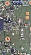
Taking a very wild guess, I would say it's probably a MOSFET in an SOT23-6 package (2.9mm x 1.6mm). Would need a clear close-up photo of the device that shows any markings to make any more semi-educated guesses.
edit: Further examination of the circuit board photo shows that there are several transistors on the board (3-terminal devices) and they're labelled with the standard "Q". Integrated circuits (ICs) generally use the "U" naming convention. So I may have to modify my initial W.A.G. and say.... "I'm not sure". There is a 5-terminal device, U54, near the top left corner. That might be some linear device like a voltage reference or regulator.
@disem I'm curious.... why the interest in this component? Are you trying to repair the board?
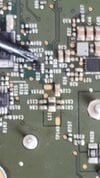
There are no markings on the on the chip. Probably erased. I am trying to identify it, because a few components are missing on some boards and in order to be able to read and modify the programmed data, those have to be present. So far I have been using chips from defective boards, but it's easier and more effective to just buy and solder new ones.
There are no markings on the on the chip. Probably erased. I am trying to identify it, because a few components are missing on some boards and in order to be able to read and modify the programmed data, those have to be present. So far I have been using chips from defective boards, but it's easier and more effective to just buy and solder new ones.
Your picture looks like there might be some very faint markings. Note some markings are almost invisible unless you shine the light at the correct angle (the U3 chip on the right using similar type of printing which is very hard to see). Take a bright LED light and shine it at various angles while looking at it at different angles. You will likely need a high power magnifying glass (using the smaller second element with higher magnification). If you need to take a picture, you may need a separate light to illuminate the component and take the picture through the lens of the magnifying glass (that's what I do with some tiny circuit board components).