I won't go into too many details re the background, but we have had A LOT of problems with this install over the last year, including 12 visits by Tesla and/or its sub-contractors in the last 7 months.
System Setup:
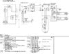
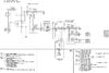
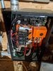
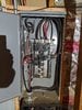
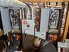
We have a 400 amp service outside that feeds a 400 amp sub-panel in our basement. To get a whole home backup, my understanding is that Tesla needed to split that 400 amp sub-panel into two 200 amp sub-panels, each with its own gateway to function correctly. We have two Powerwalls behind each gateway (four powerwalls total). We also have two solar arrays (each with its own inverter - two total), and Tesla was supposed to connect one inverter behind each gateway over the weekend.
From a graphical perspective, my understanding is that our system looks something like this:
|--200 amp sub-panel_1<-->Gateway_1<--->PV Inverter_1 / Powerwall Bank_1
400 amp service<--->400 amp sub-panel
|--200 amp sub-panel_2<-->Gateway_2<--->PV Inverter_2 / Powerwall Bank_2
I'm curious if others have this setup and how their system performs. Offhand, I'm not sure ours is functioning correctly, and I will try to explain below:
In the app, Gateway_1 and Gateway_2 are on different screens, and each have the option to be set to run as (a) Backup-Only; (b) Self-Powered; or (c) Advanced.
Backup-only:
When both Gateways are in this setting, the "Power Flow" is:
- Gateway_1 shows Solar to Powerwall; and Grid to Home.
- Gateway_2 shows Solar to Powerwall; and Grid to Home
In other words, the solar is powering the Powerwalls and the Grid is powering the house. This was expected.
Self-Powered:
When both Gateways are in this setting, only one Powerwall Bank will charge at a time (despite each being connected to a PV inverter), and the second bank will discharge to charge the first. Our "Power Flow" looked something like this:
- Gateway_1 shows Solar (7.8 kW) to Powerwall (6.1 kW); and Solar (7.8 kW) to Grid (1.7 kW)
- Gateway_2 shows Solar (4.0 kW), Powerwall (4.1 kW), and Grid (0.3 kW) to Home (5.9 kW)
The house energy consumption behind Sub-panel_1 is about 1.2 kW.
The house energy consumption behind Sub-Panel_2 is about 0.9 kW.
Each inverter should be producing about 4.0 kW (or about 8.0 kW in aggregate), so Gateway_1 is showing too much Solar production; and the "house" was certainly NOT consuming 5.9 kW.
On paper, it looks like Powerwall Bank 2 is discharging to "Home" and that is being picked up by Gateway_1 as additional "Solar". The net at our meter is actually correct, we were sending 1.4 kW back (Gateway_1 is sending 1.7 kW to the grid and Gateway_2 is pulling 0.3 kW from the grid, for a net of 1.4 kW).
No clue why this is happening, but it doesn't seem correct.
****NOTE - my numbers may not be exactly right as they were fluctuating and I had to move between two screens to capture, but hopefully this will provide some context. If we get a good solar day tomorrow, I'll see if I can run two smartphone screens simultaneously to get an accurate real-time reading and update my thread.
Advanced (Balanced):
When both Gateways are in this setting, only one Powerwall Bank will charge at a time (despite each being connected to a PV inverter) and the second remains in standby. Around Noon today, our "Power Flow" looked like this:
- Gateway_1 shows Solar (7.8 kW) to Powerwall (4.1 kW); and Solar (7.8 kW) to Grid (3.8 kW)
- Gateway_2 shows Solar (4.0 kW) to Home (5.9 kW); and Grid (0.3 kW) to Home (5.9 kW)
The house energy consumption behind Sub-panel_1 is about 1.2 kW.
The house energy consumption behind Sub-Panel_2 is about 0.9 kW.
Each inverter should be producing about 4.0 kW (or about 8.0 kW in aggregate).
We are on a TOU plan where our peak-time is from 4-9 p.m.
If our solar system was producing about 8 kW at Noon, 4.1 kW was basically going to charge Powerwall Bank 1, 2.1 kW was charging the house, and the remaining 1.8 kW was being sent back to the grid. This was surprising given that we were basically selling energy back to the grid during off-peak hours (when energy is the cheapest). Why was the system not putting more into charging Powerwall Bank 1 or charging Powerwall Bank 2?
FYI - around 2 p.m. when our solar system was generating 12-13 kW, we were sending back 5-6 kW while only one battery charged. This was a lot of wasted energy being sold back to the grid during non-peak time.
We started the day with Powerwall Bank 1 at 32% and Powerwall Bank 2 at 35%. Bank 2 charged to about 78%, then the system changed over for some reason and charged Bank 1 to about 75%. If the Gateways would have been charging the Powerwalls instead of sending energy back to the grid during off-peak (see above), both banks would have charged to 100%.
Once we hit 4 p.m. (peak time), Bank 1 discharged down to 35%, and then Bank 2 also discharged down to 35% - this was expected. But, the total amount of energy discharged during this time was only 78% to 35% and 75% to 35% because the Gateways were selling energy back to the grid during off-peak earlier in the day, as mentioned above.
****NOTE - again, my numbers may not be exactly right. I will try to gather better data in the coming days and update.
This seems completely off and defeats the purpose of having the TOU setting. I would be better off getting up in the morning, turning on "back-up only", and then manually switching to TOU at 4 p.m. to get the desired charge/discharge cycle for the day.
I've read that the Advanced setting can take some time to figure out and will adjust to home energy usage as time goes on. Note that our batteries were hooked up about a month ago and Tesla got around to hooking up the solar about 5 weeks later.
Final Thoughts
I get the feeling that Telsa wired the system incorrectly because it looks like one gateway might be back-feeding to the other gateway and producing inaccurate readings for Solar generation and Home energy usage.
As a result, it doesn't appear that the systems are completely isolated, which could be a good thing during an outage as energy could be moved from one bank to another in an outage to keep all our lights on.
I'm not sure if this is how the system is supposed to be operating, so I thought I'd see if anyone else ended up in a similar complicated situation.
System Setup:
We have a 400 amp service outside that feeds a 400 amp sub-panel in our basement. To get a whole home backup, my understanding is that Tesla needed to split that 400 amp sub-panel into two 200 amp sub-panels, each with its own gateway to function correctly. We have two Powerwalls behind each gateway (four powerwalls total). We also have two solar arrays (each with its own inverter - two total), and Tesla was supposed to connect one inverter behind each gateway over the weekend.
From a graphical perspective, my understanding is that our system looks something like this:
|--200 amp sub-panel_1<-->Gateway_1<--->PV Inverter_1 / Powerwall Bank_1
400 amp service<--->400 amp sub-panel
|--200 amp sub-panel_2<-->Gateway_2<--->PV Inverter_2 / Powerwall Bank_2
I'm curious if others have this setup and how their system performs. Offhand, I'm not sure ours is functioning correctly, and I will try to explain below:
In the app, Gateway_1 and Gateway_2 are on different screens, and each have the option to be set to run as (a) Backup-Only; (b) Self-Powered; or (c) Advanced.
Backup-only:
When both Gateways are in this setting, the "Power Flow" is:
- Gateway_1 shows Solar to Powerwall; and Grid to Home.
- Gateway_2 shows Solar to Powerwall; and Grid to Home
In other words, the solar is powering the Powerwalls and the Grid is powering the house. This was expected.
Self-Powered:
When both Gateways are in this setting, only one Powerwall Bank will charge at a time (despite each being connected to a PV inverter), and the second bank will discharge to charge the first. Our "Power Flow" looked something like this:
- Gateway_1 shows Solar (7.8 kW) to Powerwall (6.1 kW); and Solar (7.8 kW) to Grid (1.7 kW)
- Gateway_2 shows Solar (4.0 kW), Powerwall (4.1 kW), and Grid (0.3 kW) to Home (5.9 kW)
The house energy consumption behind Sub-panel_1 is about 1.2 kW.
The house energy consumption behind Sub-Panel_2 is about 0.9 kW.
Each inverter should be producing about 4.0 kW (or about 8.0 kW in aggregate), so Gateway_1 is showing too much Solar production; and the "house" was certainly NOT consuming 5.9 kW.
On paper, it looks like Powerwall Bank 2 is discharging to "Home" and that is being picked up by Gateway_1 as additional "Solar". The net at our meter is actually correct, we were sending 1.4 kW back (Gateway_1 is sending 1.7 kW to the grid and Gateway_2 is pulling 0.3 kW from the grid, for a net of 1.4 kW).
No clue why this is happening, but it doesn't seem correct.
****NOTE - my numbers may not be exactly right as they were fluctuating and I had to move between two screens to capture, but hopefully this will provide some context. If we get a good solar day tomorrow, I'll see if I can run two smartphone screens simultaneously to get an accurate real-time reading and update my thread.
Advanced (Balanced):
When both Gateways are in this setting, only one Powerwall Bank will charge at a time (despite each being connected to a PV inverter) and the second remains in standby. Around Noon today, our "Power Flow" looked like this:
- Gateway_1 shows Solar (7.8 kW) to Powerwall (4.1 kW); and Solar (7.8 kW) to Grid (3.8 kW)
- Gateway_2 shows Solar (4.0 kW) to Home (5.9 kW); and Grid (0.3 kW) to Home (5.9 kW)
The house energy consumption behind Sub-panel_1 is about 1.2 kW.
The house energy consumption behind Sub-Panel_2 is about 0.9 kW.
Each inverter should be producing about 4.0 kW (or about 8.0 kW in aggregate).
We are on a TOU plan where our peak-time is from 4-9 p.m.
If our solar system was producing about 8 kW at Noon, 4.1 kW was basically going to charge Powerwall Bank 1, 2.1 kW was charging the house, and the remaining 1.8 kW was being sent back to the grid. This was surprising given that we were basically selling energy back to the grid during off-peak hours (when energy is the cheapest). Why was the system not putting more into charging Powerwall Bank 1 or charging Powerwall Bank 2?
FYI - around 2 p.m. when our solar system was generating 12-13 kW, we were sending back 5-6 kW while only one battery charged. This was a lot of wasted energy being sold back to the grid during non-peak time.
We started the day with Powerwall Bank 1 at 32% and Powerwall Bank 2 at 35%. Bank 2 charged to about 78%, then the system changed over for some reason and charged Bank 1 to about 75%. If the Gateways would have been charging the Powerwalls instead of sending energy back to the grid during off-peak (see above), both banks would have charged to 100%.
Once we hit 4 p.m. (peak time), Bank 1 discharged down to 35%, and then Bank 2 also discharged down to 35% - this was expected. But, the total amount of energy discharged during this time was only 78% to 35% and 75% to 35% because the Gateways were selling energy back to the grid during off-peak earlier in the day, as mentioned above.
****NOTE - again, my numbers may not be exactly right. I will try to gather better data in the coming days and update.
This seems completely off and defeats the purpose of having the TOU setting. I would be better off getting up in the morning, turning on "back-up only", and then manually switching to TOU at 4 p.m. to get the desired charge/discharge cycle for the day.
I've read that the Advanced setting can take some time to figure out and will adjust to home energy usage as time goes on. Note that our batteries were hooked up about a month ago and Tesla got around to hooking up the solar about 5 weeks later.
Final Thoughts
I get the feeling that Telsa wired the system incorrectly because it looks like one gateway might be back-feeding to the other gateway and producing inaccurate readings for Solar generation and Home energy usage.
As a result, it doesn't appear that the systems are completely isolated, which could be a good thing during an outage as energy could be moved from one bank to another in an outage to keep all our lights on.
I'm not sure if this is how the system is supposed to be operating, so I thought I'd see if anyone else ended up in a similar complicated situation.