Can I ask a new question about Tesla charging. I just ordered the new Tesla Universal charger and I have become so confused about max amp draw for a setup and have seen mixed information.
This is what I have done.
A) Tesla hardwired wall charger has two hot wires (Red an black) and ground (green). White or neutral is not needed.
B) I spend a while setting up my detached garage running 11/4 rigid conduit underground (live in Chicago area) and at a junction box split to two 3/4 conduit to two separate sites in my garage to "future proof" my setup since I will only need one now.
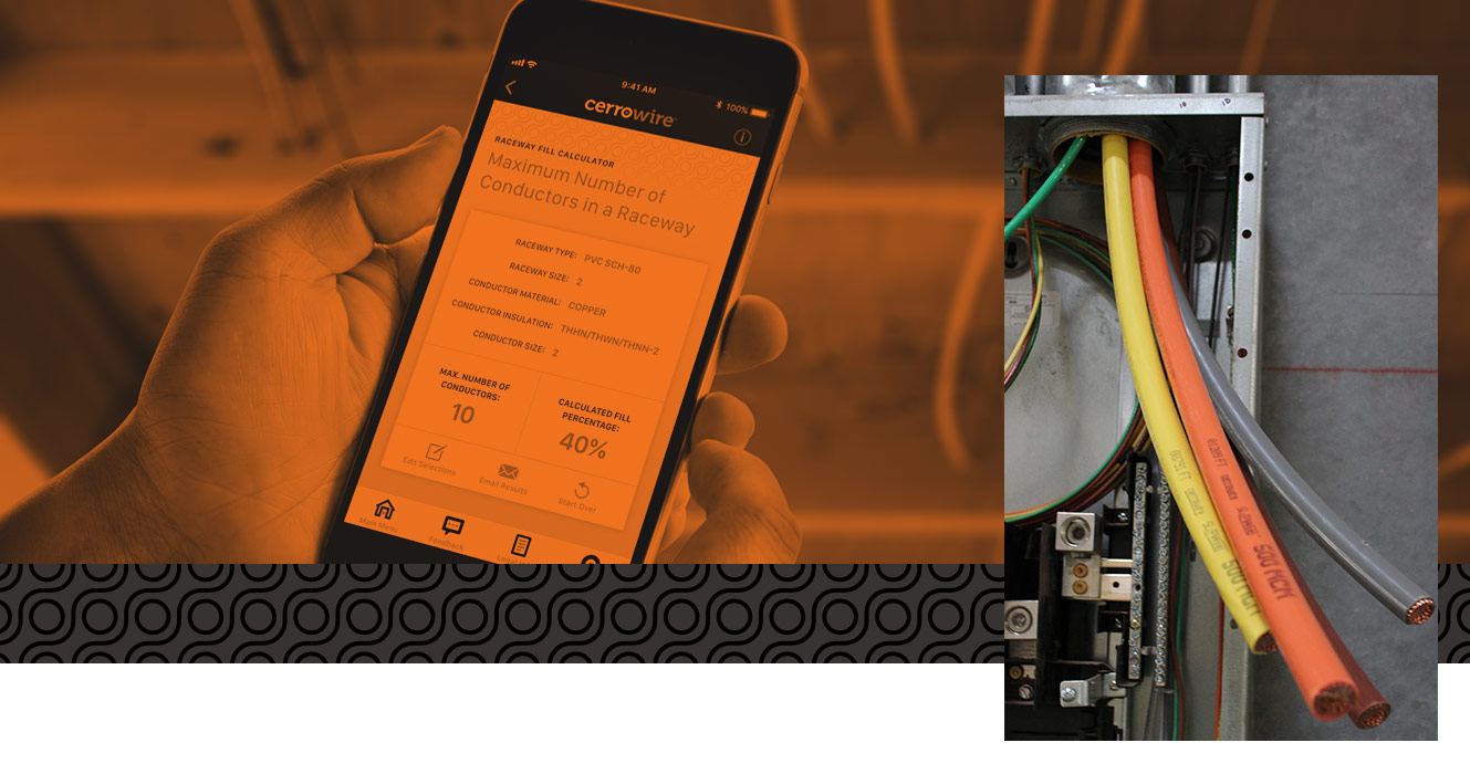
C) I am using 6awg THHN / THWN-2 wire from a 60 am non-ground fault breaker going 120 feet without interruption directly to a wall charger. I installed 6 wires. Two red, two black and 2 green.
D) I read this from Tesla,
E) I will be tightening the wires accounting to the torque requirements.
My questions are as follows.
1) what is L2/N. I are mostly confused about the /N. Do I need a neutral?
2) Being less than 150ft at 220V I believe the amp rating is unchanged but can my setup pull 48 amps continuous? I have seen so many different rating for Romex, THHN at 6awg that I am confused. 80% max limitation for continuous load but what is my max?
3) Any issue with putting two 60amp circuits on the same 200 amp Panel next to one another?
4) Should I have used 4awg to get the full 48 amps continuous? if so I would need to change the 3/4 conduit to 1 inch.
Help.
This is what I have done.
A) Tesla hardwired wall charger has two hot wires (Red an black) and ground (green). White or neutral is not needed.
B) I spend a while setting up my detached garage running 11/4 rigid conduit underground (live in Chicago area) and at a junction box split to two 3/4 conduit to two separate sites in my garage to "future proof" my setup since I will only need one now.
C) I am using 6awg THHN / THWN-2 wire from a 60 am non-ground fault breaker going 120 feet without interruption directly to a wall charger. I installed 6 wires. Two red, two black and 2 green.
D) I read this from Tesla,
- For sites with multiple Wall Connectors, each Wall Connector must have its own branch circuit with L1,
L2/N, and Ground.
E) I will be tightening the wires accounting to the torque requirements.
My questions are as follows.
1) what is L2/N. I are mostly confused about the /N. Do I need a neutral?
2) Being less than 150ft at 220V I believe the amp rating is unchanged but can my setup pull 48 amps continuous? I have seen so many different rating for Romex, THHN at 6awg that I am confused. 80% max limitation for continuous load but what is my max?
3) Any issue with putting two 60amp circuits on the same 200 amp Panel next to one another?
4) Should I have used 4awg to get the full 48 amps continuous? if so I would need to change the 3/4 conduit to 1 inch.
Help.