Welcome to Tesla Motors Club
Discuss Tesla's Model S, Model 3, Model X, Model Y, Cybertruck, Roadster and More.
Register

HPWC IR Pics (more fun!)

This site may earn commission on affiliate links.
But for heat I'm guessing it's a lot better to pull 20 kW at 32A instead of 80A.

It is easier to design in that your wires and connector pins don't have to as thick. But Tesla could have designed the HPWC with more margin for error, the cable would have been thicker, and the HPWC would have to be bigger. Maybe they should have? OTOH, I've heard many more stories of Tesla UMC adapters overheating than I have of the HPWC overheating. Overall, the HPWC seems to work well.
 
It is easier to design in that your wires and connector pins don't have to as thick. But Tesla could have designed the HPWC with more margin for error, the cable would have been thicker, and the HPWC would have to be bigger. Maybe they should have? OTOH, I've heard many more stories of Tesla UMC adapters overheating than I have of the HPWC overheating. Overall, the HPWC seems to work well.

I think thats just statistics. Everyone has a UMC, not everyone has a HPWC.
 
Wow! Great images and great analytics. I was seeing similar issues with the standard UMC, but my data collection pales in comparison. :smile:

Like wk057, Tesla took care of it right away. Below is my post from the "Hot UMC Cable" thread . . .

Just picked up my car today from the Service Center - another very positive experience (Go Tesla!). I had scheduled the appointment a while back for tire rotation and other checks, but when I shared my cable temperature data (see below), the Service Manager asked me to bring in my UMC cable to be checked as well. The conclusion was that the cable was indeed running hotter than normal under their controlled test conditions and thus they replaced it at no charge. Here are some quick takeaways for the community . . .

* The SCs appreciate detailed data, but must doublecheck themselves to confirm issues (understandable)
* There isn't a specific temperature limit or threshold above which the cable is known bad. Reason is that we all charge our cars under different environmental conditions (e.g. ambient temp, sun/no sun, nearby appliances, etc.) and thus there is some reluctance to set one guideline
* Nonetheless, with a check at the SC, and cross-check to a known-good cable under the same exact conditions, they can quickly etermine if the cable is good or bad
* General Guidance (mentioned as well by other posts): If the cable is warm, that is normal; if the cable is hot such that you cannot hold it in your bare hand for any length of time, then it should be checked.

When I have more time, I'll measure the temps on the new UMC cable for comparison. In the meantime, for those who like data, this is for you . . .

View attachment 56008
 
Metal Conduit Vs. Romex:
I also wired my system with 2AWG copper wire, and I also noted that the 6AWG Rubber cord at the HPWC exit and at the Connector Handle were the hottest areas per my un-calibrated hands.
A friend of mine installed his 2AWG wiring using metal Conduit. I used Romex in the wall without conduit. I still need to close the sheetrock, so the Romex is still exposed for inspection. I noticed that my friend’s 1” metal conduit entering the HPWC was very very hot to the touch. There was also 1-1/4” conduit used to reach a junction box close by. This conduit was slightly cooler. My 2AWG Romex entering the HPWC was barely warm. In both cases I was charging my empty Model S at 80Amps for a good hour or more. Both of our HPWCs have the new larger fuses.
So I am wondering how much inductive heating is being added by the small diameter metal conduit? I do have some metal conduit , 5 feet of 1-1/2”, where the Romex (stripped jacket) exits the attic and goes to the main electrical panel. During the same charge session at night, it was cool to the touch. Bigger conduit is better.

Out of curiosity since you're the first person I've seen say they actually used Romex to install the HPWC what Romex did you use exactly? Actual Romex (as in what is made by Southwire, though lots of people refer to anything like it as Romex) with 2 AWG conductors as far as I can tell is only usable for up to 95 amperes. See this: http://www.southwire.com/ProductCatalog/XTEInterfaceServlet?contentKey=prodcatsheet6
 
Tested out the replacement HPWC with pretty close results. Oddly enough the handle at the car was a bit cooler than my previous one, so, I'll go with it.

So, I wanted to get some good measurements of voltages at multiple points along the way. At 80A charging this is what I saw (this was in the middle of the day, no ToU metering at this location... voltages are easily 10V higher at night):

  • 234V @ Model S Dash readout
  • 236.0V @ junction inside HPWC heading towards car
  • 236.4V @ 2AWG copper input to HPWC
  • 238.2V @ Panel

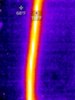
This comes to about 4.2V @ 80A of resistive heating loss, or about 336 watts. Not negligible, but, my 2AWG run is roughly 30ft. The HPWC cable is 25ft, so, about 6.1 watts per foot average heat generation in the wiring. ~6.4W/ft in the HPWC->Car cable, ~5.76W/ft in my 2AWG cable... so, nearly the same resistive losses, which explains the warm conduit. No where near any unsafe temp, however.

336W may not seem like much, but it does add up in an insulated cable over time. At these currents, though, it is expected there will be some loss to heat unless we're talking about some ridiculous gauge wiring.

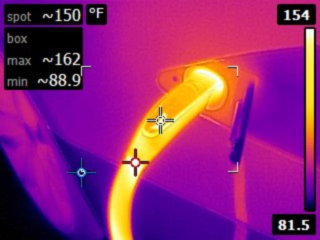
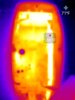
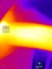
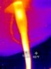
So, here is a baseline, a couple of minutes into charging @ 80A:

View attachment 55883View attachment 55884View attachment 55885View attachment 55886

I checked back 30 minutes later:
View attachment 55887View attachment 55888View attachment 55889View attachment 55890View attachment 55891View attachment 55892View attachment 55893View attachment 55894View attachment 55895

And about 30 minutes later again:
View attachment 55896View attachment 55897View attachment 55898View attachment 55899View attachment 55900View attachment 55901View attachment 55902View attachment 55903

-----

So, some notes.

This time I left the protective plastic on the cover for the HPWC... I figure this would help with the FLIR cam a bit and not just register reflections. Seems to have worked, so, pics here with the cover on have the film on.
I also kept the cover installed during charging. I removed it each time I was taking pictures. Also, this is the brand new replacement HPWC that Tesla service mailed to me. I started the switch last night and finished the install this morning.

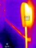
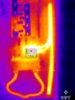
Next... that resistor scares me. Was almost 300F... and was already 275F at the start of the charge. It's just a resistor, but seems like it's under a pretty decent load for whatever reason...

There is some wiring inside that is well above 105C... not particularly safe for continuous use. And these pics are only after about an hour of charging... I hadn't charged for a couple of days since I received the replacement HPWC, but hadn't driven much... just about 100 miles.

In summary, my thoughts:
  • I think resistive losses in the home wiring is acceptable.
  • I think resistive losses in the HPWC->Car wiring is pretty close to acceptable, but probably would be an issue if a HPWC was under continuous use (for example, charging two Model S one after another...)
  • To make the handle and external wiring cooler would require heavier (gauge and weight) wiring
    • The wire is already pretty heavy, weight wise...
  • The internals probably should be a bit beefier.
    • At a minimum I'd say 2AWG wiring from the contactor to the junction to the charge cable.
      • Have this spot sink the resistive heat that will linger here somewhere...
    • The contactor itself is possibly underrated for this and might benefit from being a notch more heavy duty
    • Perhaps a small cooling fan?
      • Guess this would prevent weatherproofing, so maybe a design that includes some fins for a heat sink
  • It will suffice for now.

I doubt we're going to see an overhaul anytime soon, so, it will suffice. I'm not afraid of it bursting into flames or anything, but, I am going to keep an eye on it.
Long term, since the warranty on the HPWC is only 1 year, I'll probably gut it and make an openEVSE type control board to put in there, a heavier contactor, and some heavier internal wiring. Also probably shorten the external cable slightly to fit my needs. Probably a PITA all together, but would make me feel better long term. Besides, can do plenty of cool stuff when you can program the controller yourself.

Long term I'd like to see Tesla completely redesign this thing and I'd buy an upgraded one in a heartbeat.

Outstanding post.
Pretty much confirms my Strategy; if you want the HPWC to last you will want to dial down the daily overnight charge current so it will operate cooler.
http://www.teslamotorsclub.com/showthread.php/48097-HPWC-Reliability-an-Overnight-Charging-Strategy

I can confirm the anticipated 50mv max drop across the contactor (earlier reply) as I measured a total HPWC internal voltage drop of 47mV across each leg of input to output terminals. That is only 0.5 mOhms on each leg which is impressive.

However, that much heating is not from the internal 8 watts IR loss; so I anticipate there is some significant Eddy current heating effects occurring. Something that would not occur in the contactor's DC spec'ed application!!

It would also be nice to see the FLIR images at 64, 40, 32 amps just to see how much cooler it is when the current is turned down on the charging console!!

Thanks for the huge effort...
 
Last edited:
wk057, quick question for those of us not so savvy - to dial down the amount of power being used; can I leave my HPWC wired as is (set up for 80 amps) and just change the toggle switches inside to a lower setting or do I have to change the rest of the wiring set-up?

I've only had the car a couple of days but I really don't need to charge in mere hours, overnight would be just fine especially if it lessons the load on the entire system z(as well as heat generated).

Thanks for your help!
I, personally, wouldn't mess with the toggles in the HPWC if it is set up safely to code. Rather just set the amperage you want on the controls for charging inside the car. Set to 40 amps if you wish. It will stay at that unless/until you change it for that location.
 
I, personally, wouldn't mess with the toggles in the HPWC if it is set up safely to code. Rather just set the amperage you want on the controls for charging inside the car. Set to 40 amps if you wish. It will stay at that unless/until you change it for that location.

I like 56 Amps to cut all the resistive losses and temperature rises in half. I just set it in the car, and have no qualms about using 80 Amps when I am in a hurry. I would not set the current to below 44 Amps on a regular basis. At more than 40 Amps, both charging modules are tested, and there have been cases of folks always charging at 40 Amps, and then wanting fast charging on a trip found out the second charger was dead. It's good to test both and spread the heat load across both. It seems that the MS divides the current across the two chargers when the total is above 40 Amps.

Like I said, I like 56 Amps as a sweet spot for daily charging; 50% of the heat and 70% of the charge rate...

I certainly would not change the DIP settings in the HPWC. Leave the max current available when you need it!
 
I like 56 Amps to cut all the resistive losses and temperature rises in half. I just set it in the car, and have no qualms about using 80 Amps when I am in a hurry. I would not set the current to below 44 Amps on a regular basis. At more than 40 Amps, both charging modules are tested, and there have been cases of folks always charging at 40 Amps, and then wanting fast charging on a trip found out the second charger was dead. It's good to test both and spread the heat load across both. It seems that the MS divides the current across the two chargers when the total is above 40 Amps.

Like I said, I like 56 Amps as a sweet spot for daily charging; 50% of the heat and 70% of the charge rate...


I certainly would not change the DIP settings in the HPWC. Leave the max current available when you need it!

Cottonwood, thanks once again for the help. I'll actually be back in Colorado Springs this weekend for a wedding; I was born and raised there so always great to come back home for a little bit.
 
Adjusted everything as recommended and am amazed at the reduction in heat and the estimated charge time really didn't increase much at all. Especially when I am just doing overnight charging or my commute, not in a hurry to add the miles back in.

Good stuff, thanks again.
 
Digging up my old thread for an update...

Burn reflex when removing the HPWC today. :(

FLIR0804-HPWC-Handle.jpg


(I put a sticker on the handle so the aluminum wouldn't reflect IR and show up cool on the FLIR)

I regularly (every few months) clean the contacts on both the car and the HPWC. I've had two installed for over two years now.

They're out of warranty now, but probably going to contact Tesla to see if the newer ones have better cabling or not yet.
 
  • Informative
Reactions: XLR8OR and hiroshiy
Well, that is a bummer. I didn't realize there were issues/concerns with heat on these but it makes perfect sense that the risks are there.

Did this below contact stud topic get closed? I've seen threads about if there is a right side up to install the HPWC, but this is the first I've seen about a concern of the direction...

A concern from the datasheet: "If mounted vertically the contact studs must point upward." The HPWC does the opposite of this. :( The consequences, I would guess, would be less pressure on the contacts, resulting in higher resistance, which could account for the increased heat I was seeing prior. The coil even on the least efficient configuration of this contactors dissipates 20W, which wouldn't account for the temps I was seeing alone. The contactor is also rated for only a 50mV drop across the contacts... so 4W of heat at 80A.

I will still install and test the replacement unit before contacting Tesla and inquiring about a potential design error...

(Not sure if I should have made this a new thread...)
 
Well, that is a bummer. I didn't realize there were issues/concerns with heat on these but it makes perfect sense that the risks are there.

Did this below contact stud topic get closed? I've seen threads about if there is a right side up to install the HPWC, but this is the first I've seen about a concern of the direction...

HPWCv2 is much better built and not someone's bad science project, it also appears to have temperature sensors in the handle, which v1 does not. I'd post IR pics but still waiting for my dual charger install. 8th week here we go.
 
  • Like
Reactions: hiroshiy
Ok HPWCv2 is still quite hot. However, the solenoid isn't the hottest part, but it's the cable leads themselves. Temps maxed out around 1.5 hours.
 

Attachments

  • IMG_6535.JPG
    IMG_6535.JPG
    43.5 KB · Views: 77
  • IMG_6530.JPG
    IMG_6530.JPG
    34.7 KB · Views: 58
  • IMG_6529.JPG
    IMG_6529.JPG
    38.2 KB · Views: 72
  • IMG_6528.JPG
    IMG_6528.JPG
    50.5 KB · Views: 73
  • IMG_6527.JPG
    IMG_6527.JPG
    40.6 KB · Views: 62
  • IMG_6520.JPG
    IMG_6520.JPG
    52.8 KB · Views: 68
  • Informative
Reactions: hiroshiy