Hey all,
Long time lurker - first time poster.
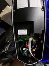
Long story short, recently my Wall Charger fried. After opening it up I clearly saw the culprit (see photos).
What I would like to discuss is if the hired electrician did a good job or if there is negligence on the hired electricians part. I'm by no means am a electrician and I took my contractors recommendation. This contractor has worked on my house multiple times so I trusted his word . The hired electrician wasn't Tesla Certified at the time. (Still don't know if the company is or isn't.) But at the very least they are a licensed electrician.
So here are my facts and see the photos for visual details.
Timeline/Usage
So roughly around 3.5 years of service.
Possible Negligence Areas
Thank you all for participating in this discussion. I appreciate any help/advice that you'll leave.
Long time lurker - first time poster.
Long story short, recently my Wall Charger fried. After opening it up I clearly saw the culprit (see photos).
What I would like to discuss is if the hired electrician did a good job or if there is negligence on the hired electricians part. I'm by no means am a electrician and I took my contractors recommendation. This contractor has worked on my house multiple times so I trusted his word
. The hired electrician wasn't Tesla Certified at the time. (Still don't know if the company is or isn't.) But at the very least they are a licensed electrician.So here are my facts and see the photos for visual details.
Timeline/Usage
- The Wall Charger was installed back in Nov 2017.
- I received my Model 3 in June 2018.
- August 2020 - May 2022 I was living in Indiana and only used the charger during the summer/winter breaks. (I was in Indiana for graduate school).
So roughly around 3.5 years of service.
Possible Negligence Areas
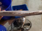
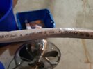
- The conductors used were aluminum. It clearly states in the manual and on the hardware use copper conductors only.
- The hired electrician didn't acquire a permit from the town. Thus didn't submit plans of the work to the town. I wasn't aware this was necessary but am now after getting estimates from Tesla certified electricians for installing a new Wall Charger.
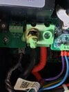
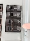
- The break installed is an 80amp breaker and I heard from some friends that could cause a problem in the case of power surge scenarios. I'm not necessarily sure I understand this one and more explanation would be greatly appreciated. Something along the lines of if a surge did happen and the breaker wasn't trip, 80 amps would be sent to the Wall Charger which is a 60 amp unit. Thus, receiving more power than it's intended, is this correct?
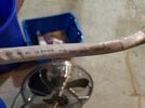
- Fried Internals
- Fried Internals with Copper Conductor sticker
- Installed breaker
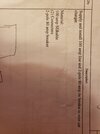
- Outline of work on original estimate
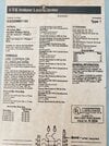
- Main Breaker information sticker
Thank you all for participating in this discussion. I appreciate any help/advice that you'll leave.

 Thank you!